- 您现在的位置:买卖IC网 > Sheet目录338 > LV5217GP-TE-L-E (ON Semiconductor)IC LED DVR 3CH CELL PHONE VCT16
LV5217GP
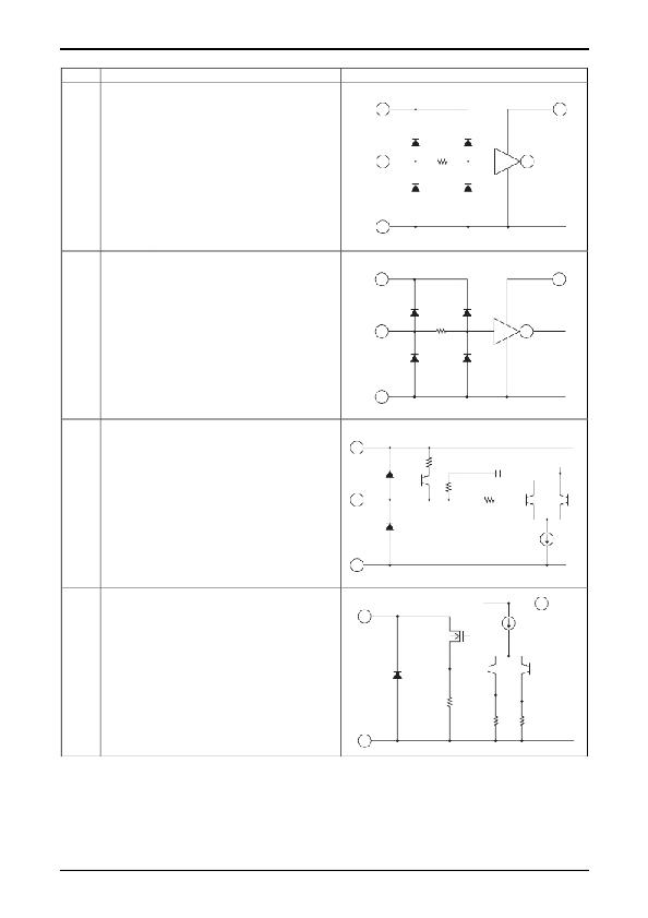
Pin Functions
Pin No.
Symbol
Description
Equivalent circuit
4
LEDON
Control inputs for the three external colored LEDs.
When an RSW, GSW, or BSW bit in the serial data
VCC
VDD
is set to 1, the corresponding LED will be on when
the voltage applied to the corresponding pin is high,
and off when the voltage applied is low.
LEDON
10k Ω
GND
8
9
SDAI
SCLI
I 2 C signal inputs
VCC
VDD
Each input
10k Ω
GND
3
RT
Reference current setting resistor connection.
A reference current is created by connecting an
VCC
external resistor between this pin and ground. The
pin voltage is roughly 1.2V. The LED driver current
can be changed by changing this current value.
RT
35k Ω
30pF
10k Ω
GND
14
15
RLED
GLED
Driver outputs for the three color LEDs.
Feedback is applied to control the current flowing in
16
BLED
the output transistors to be the set value. Each of
the driver output current levels can be set
RLED
VCC
independently with the serial data.
5 Ω
GND
Continued on next page.
No.A0833-4/12
发布紧急采购,3分钟左右您将得到回复。
相关PDF资料
LV8498CT-TE-L-H
IC MOTOR DRIVER S111 WLP
LXC100-4200SW
POWER SUPPLY LED 100W 4200MA
LXC120-4900SW
POWER SUPPLY LED 120W 4900MA
LXC150-5950SW
POWER SUPPLY LED 150W 5950MA
LXC25-2080SW
POWER SUPPLY LED 25W 2080MA
LXC35-2900SW
POWER SUPPLY LED 35W 2900MA
LXC40-3330SW
POWER SUPPLY LED 40W 3330MA
LXC50-4200S
POWER SUPPLY LED 50W 4200MA
相关代理商/技术参数
LV5219LG
制造商:SANYO 制造商全称:Sanyo Semicon Device 功能描述:For cell phone LED driver
LV5219LGL-MPB-H
制造商:ON Semiconductor 功能描述:MULTI-FUNCTION LED DRIVER
LV5219LGL-TLM-H
制造商:ON Semiconductor 功能描述:REEL / MULTI-FUNCTION LED DRIVER
LV5219LG-MPB-E
制造商:ON Semiconductor 功能描述:MULTI-FUNCTION LED DRIVER - Trays 制造商:ON Semiconductor 功能描述:LED Lighting Drivers MULTI-FUNCTION LED DVR 制造商:ON Semiconductor 功能描述:JTRAY / MULTI-FUNCTION LED DRIVER
LV5219LG-TLM-E
制造商:ON Semiconductor 功能描述:MULTI-FUNCTION LED DVR 制造商:ON Semiconductor 功能描述:REEL / MULTI-FUNCTION LED DRIVER
LV5219LG-TLM-H
制造商:Rochester Electronics LLC 功能描述: 制造商:ON Semiconductor 功能描述:REEL / MULTI-FUNCTION LED DRIVER 制造商:Sony Semiconductor Solutions Division 功能描述:
LV52204MUTBG
制造商:ON Semiconductor 功能描述:LED - Tape and Reel
LV52205MUTBG
制造商:ON Semiconductor 功能描述:LED - Tape and Reel 制造商:ON Semiconductor 功能描述:REEL / LED